Welcome to the website of Hebi Yuxing Coal Machinery Co., Ltd.!
Hotline:


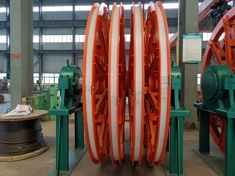
Operation, Maintenance, and保养 of Multi-Rope Friction Hoist Sheave Systems
2024-02-19
Maintenance, Operation, and Care Guidelines for Multi-Rope Friction Hoist Sheave Systems:
The hoist sheave assembly, installed on the derrick and exposed to rain and snow, operates under harsh conditions. Therefore, it’s crucial to pay extra attention to regular lubrication, ensuring smooth relative rotation between each traveling sheave and its shaft, and maintaining adequate oil supply in the rolling bearings.
1. Bearings
A. During operation, special attention should be paid to bearing maintenance. Ensure that the grease remains clean at all times, and it is recommended to use either lithium-based grease #2 or #3.
B. Regularly replenish the bearing with grease—recommended once every quarter. Under normal conditions, the bearing should be fully filled, occupying 1/3 to 1/2 of the space within the bearing housing.
C. The grease in the bearing should be completely replaced once a year. When cleaning, remove the small cover on top of the outer end cap, inject kerosene, and slowly start the machine to allow the bearing to rotate gently. This will dissolve the old grease into the kerosene. Next, open the drain plug at the bottom of the bearing end cap to release the mixture of old grease and kerosene—collect it in an external container until all the old grease has been thoroughly flushed out. Finally, refill the bearing with fresh grease and reattach the end cap according to the manufacturer’s instructions.
D. During operation, the bearing's condition should be regularly inspected and observed. If any abnormal noises or irregular operation are detected, the equipment should be stopped to check the cause and handle it promptly.
2. Bearing Bushing
A. During operation, the copper bushings must maintain proper lubrication conditions. The material of the copper bushings is ZCu/N 38 Mn 2 Ph 2, while the sheave shaft is typically made from 45 steel (or high-quality alloy structural steel). For lubrication, use either lithium-based grease grade 2 or grade 3#. At least once a week, each lubrication point should be greased—ensure the lubrication point is positioned below during the process. Use a manual grease gun (supplied with the product) or an electric grease pump (provided by the user) to apply the grease. Additionally, remember to thoroughly lubricate the copper bushings upon initial installation and verify that the grease supply lines are clear and unobstructed.
Product Taboo
The procedure for lubricating with a pressure-type grease gun is as follows:
a. Remove the plug M10×1 from the lubrication point.
b. Remove the pump body from the fuel nozzle, then pull out the lever so that the lever’s groove snaps into the “8”-shaped hole on the rear cover.
c. At this point, load the grease into the tube, taking care to minimize air entrainment during filling.
d. After filling the tube with grease, screw on the pump body—but don’t tighten it completely yet. At this point, push the pull rod back into the tube to expel any air trapped inside, and then finish tightening the pump body.
AP
e. Unscrew the small sleeve from the nozzle, then use the nozzle—along with the grease gun—to thread an M10×1 stud into the sheave lubrication system.
To perform the oiling operation, simply reciprocate the pushrod into the M10×1 internal thread of the hole.
After finishing fueling, remove the nozzle, place it back exactly where it was, and securely plug the fuel inlet hole with an M10×1 screw plug to prevent dirt and dust from entering.
B. When the copper bushings wear out and need replacing, first clean the new bushings thoroughly. Begin by replacing the lower half-bushing of the outermost wheel (ensuring all clearance between the bushing and the shaft remains at the bottom). Next, screw the bolts into the threaded holes on the copper bushings. At the same time, gently push outward along the 4mm-wide circular groove radially located at the end face of the bushing—this groove was purposely left during manufacturing. Carefully remove both halves of the outer bushing assembly from the wheel hub.
Once removed, apply the recommended grease to the new bushings as required, then gently press them axially into the wheel hub using a hammer or mallet. Finally, tighten the securing bolts securely. Slowly rotate the wheel to position the original upper half-bushing at the bottom, and repeat the process to replace the remaining half-bushing.
After completing this step, shift the entire wheel one-half rope distance toward the right side, and use the same method to replace the two half-copper bushings on the left side.
With the first wheel’s copper bushings successfully replaced, proceed in the same manner to overhaul all the remaining bushings on the other traveling wheels.
3. Padding
A. Regularly inspect the lining blocks in the wheel grooves, ensuring they remain securely wedged and show no signs of loosening.
B. Regularly inspect the pressure plates at the opening of each wheel flange groove for looseness, and check whether the anti-loosening wires are rusted or broken. If any of these issues are detected, address them promptly.
When the pad wears down to a depth equal to one wire rope diameter, or when wear along the side reaches half the diameter of the wire rope, or when the remaining thickness of the pad after wear drops to half the diameter of the wire rope—any one of these three conditions requires the pad to be replaced.
D. It is recommended to install rain and sun protection facilities on the winch frame as much as possible, in order to improve the operating conditions of the winch system.

Follow us

Hebi Yuxing Coal Machinery Co., Ltd.
Hotline:+86-13939219076
Technical Consultation:+86-13503925535
Address: Yuxing Industrial Park, Shancheng, Hebi City, Henan Province
You are a helpful assistant.


Copyright © Hebi Yuxing Coal Machinery Co., Ltd. SEO tags Business license


Copyright © Hebi Yuxing Coal Machinery Co., Ltd.Business license
This website supports IPv6 and SEO tags.