Welcome to the website of Hebi Yuxing Coal Machinery Co., Ltd.!
Hotline:

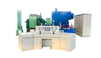
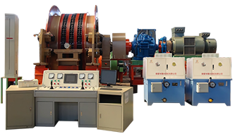

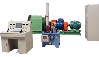

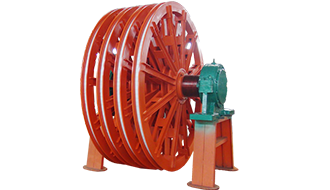
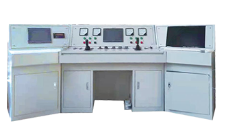
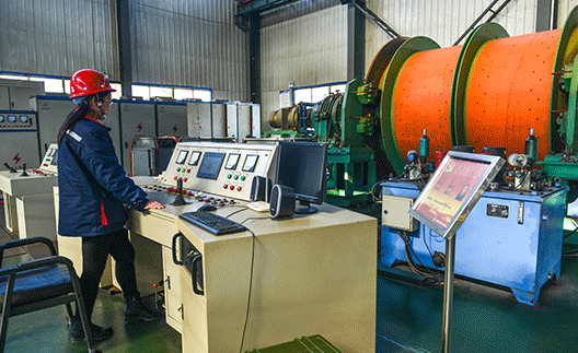
JTP-1.6 × 1.5 Hoisting Winch_JTP1.6 × 1.2 Mining Winch
2024-02-19
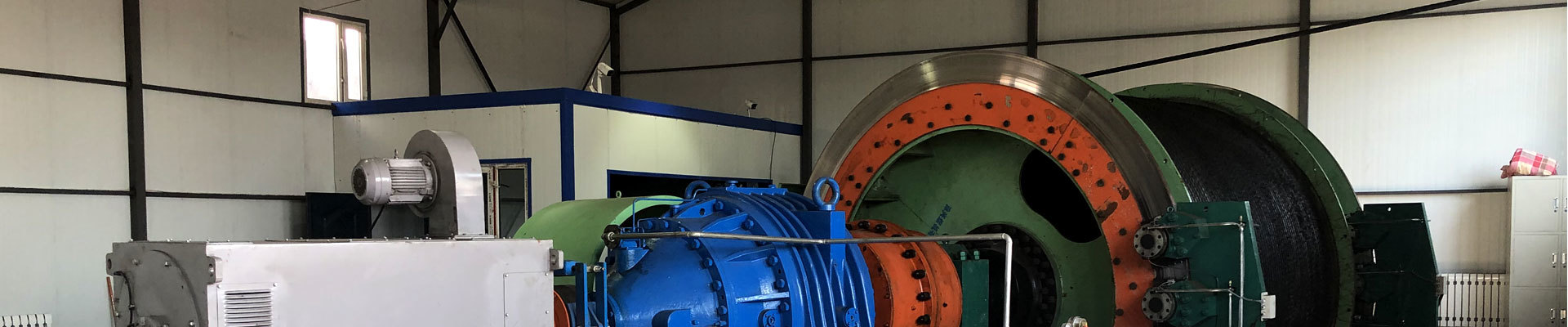
The JTP-1.6×1.5 hoisting winch main shaft assembly primarily consists of components such as the main shaft, brake wheel, support wheels, support hubs, brake hubs, drum, lining plates, sprockets, bearings, and bearing housings. Before installing and commissioning the entire 1.6-meter winch unit, all tubing and valve assemblies must be thoroughly cleaned to ensure that no solid contaminants—such as metal chips, casting sand, welding slag, or dust—are left behind in the system. In the 1.6-meter mining hoist winch, the brake hub is connected to the main shaft via a press-fit interference fit, while the brake hub is bolted to the brake wheel, and the brake wheel is secured to the drum using precision-machined bolts.

The operation is smooth, and the hoist demonstrates excellent controllability in acceleration, deceleration, and speed regulation, making seamless ramp-up and increased productivity a tangible reality. Overall energy savings can exceed 35%. The drum is connected to the brake hub and brake wheel via mating surfaces of clamping bolts, transmitting torque through shear and compressive stresses—enabling the hoist to lift and lower loads efficiently. Additionally, the hoist’s main shaft assembly, gearbox, and motor are all equipped with robust metal bases, ensuring high mechanical strength and simplifying the installation and commissioning process for the 1.6-meter hoist.
JTP1.6 × 1.2 Mine Winch: Performance and Features
1. Features high starting torque, reaching up to twice the rated torque. It boasts strong overload capacity, ensuring safe and reliable lowering of heavy loads.
2. The hoist is started and stopped via electrical system control, so the mechanical brake is only engaged after the hoist has come to a complete stop. This minimizes wear on the mechanical brake, significantly reducing costly maintenance expenses.
3. Key features of this reducer: lightweight and compact in size. It offers a wide range of transmission power, comes in various assembly configurations, can be installed on multiple sides, and is highly versatile.
4. The energy previously lost as heat in the mechanical brake system (in the old system) is now fed back into the AC grid, resulting in direct energy savings.
5. Operation is smooth, with excellent controllability over the elevator's acceleration, deceleration, and speed adjustment—making seamless ramp-up and increased productivity a reality. Overall energy savings can exceed 35%.

Disc brakes are a critical component of the hoisting mechanism's braking system. This particular hoisting brake system consists of two disc brakes, each equipped with multiple pairs of disc calipers arranged symmetrically around the rim of the brake wheel—specifically, on either side of the main shaft. Half of these calipers serve as primary brakes, while the remaining half are dedicated to secondary braking. The delay time for the secondary braking function is precisely controlled by solenoid valves managed through the electric control system.
JTP1.6 × 1.2 Mining Winch: Product Applications and Scope of Use
Primarily used in mines containing explosive gases such as methane-air mixtures and coal dust. It is designed for lifting coal, waste rock, transporting personnel, lowering materials, tools, and equipment—making it the ideal equipment for installation in underground coal mines or other environments with flammable substances. Additionally, it can be employed in metal mines, non-metallic mines, metallurgical plants, construction sites, ports, and other engineering projects for lifting, hoisting, and material handling tasks.
Starting the JTP-1.6*1.5 hoisting winch in the mine:
1) After receiving the go-ahead signal to start, move the safety gate to the release position.
2) Determine the lifting direction based on the container position indicated by the signal and depth indicator, then operate the working gate to the release position and push the master controller to the first starting step to initiate the startup process.
3) Based on the current conditions, operate the master control to accelerate all lifting time mechanisms to the specified speed, ensuring they reach their normal rotational rate.

Follow us

Hebi Yuxing Coal Machinery Co., Ltd.
Hotline:+86-13939219076
Technical Consultation:+86-13503925535
Address: Yuxing Industrial Park, Shancheng, Hebi City, Henan Province
You are a helpful assistant.


Copyright © Hebi Yuxing Coal Machinery Co., Ltd. SEO tags Business license




Copyright © Hebi Yuxing Coal Machinery Co., Ltd.Business license
This website supports IPv6 and SEO tags.