Welcome to the website of Hebi Yuxing Coal Machinery Co., Ltd.!
Hotline:

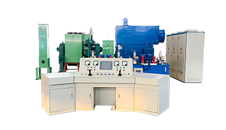
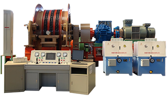

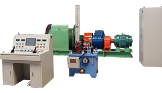

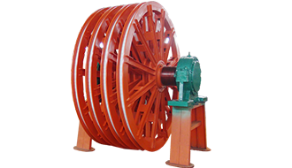

JKM Shaft-Type Multi-Rope Friction Hoist
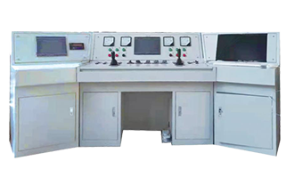
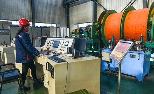
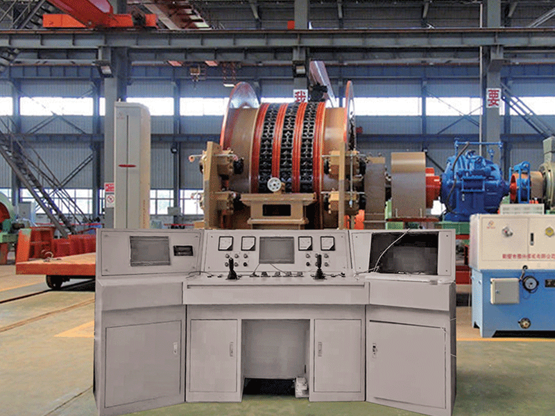
The multi-rope friction hoist primarily consists of an electric motor, a gearbox, a friction sheave, a braking system, a depth indicator, a speed-limiting system, and a control system, and is driven by either an AC or DC motor. When a low-speed motor is used, a gearbox can be omitted entirely—allowing the motor to connect directly to the drum’s main shaft, or even positioning the motor rotor at the end of the drum shaft.
Category:
Multi-rope friction hoist
Leave a Message Online
Product Description
Product Overview
The multi-rope friction hoist primarily consists of an electric motor, a gearbox, a friction sheave, a braking system, a depth indicator, a speed-limiting system, and a control system, and is driven by either an AC or DC motor. When a low-speed motor is used, a gearbox can be omitted entirely—allowing the motor to connect directly to the drum’s main shaft—or the motor rotor can even be mounted directly onto the end of the drum’s main shaft.
The braking system is a critical component that ensures the safe operation of the hoist. In emergency situations, the braking system should generate two-stage safety braking via a hydraulic system capable of adjusting brake torque, enabling the hoist to stop promptly without causing abrupt or excessive braking forces. For hoists driven by AC motors, the braking system must also feature highly responsive and adjustable brake torque capabilities, allowing precise control of the hoist's speed as it approaches the stopping point.
Uses and application scope of the product
Multi-rope friction hoists are classified into shaft tower-type and floor-standing types based on their installation method, and are primarily used in coal mines, metal mines, and non-metallic mines for lifting materials, personnel, and equipment in vertical shafts.
Since the electrical equipment supplied with this product is non-explosion-proof, it cannot be used in areas where flammable or explosive substances such as gas are present.
Product Execution Standard
JKMD. The JKM multi-rope friction hoist series products are designed and manufactured in compliance with AQ1036-2007 "Safety Inspection Specifications for Multi-Rope Friction Hoists Used in Coal Mines," Q/YX007-2021 "Multi-Rope Friction Hoist," GB/T10599-2010 "Multi-Rope Friction Hoists," as well as the "Coal Mine Safety Regulations" GB16423-2020 and the "Safety Regulations for Metal and Non-Metallic Mines."
Product Model Example

Example 1: For a friction wheel with a diameter of 3.5 m, featuring 4 steel ropes and driven by a single motor with a gearbox for resistance-based speed control, the product model of the shaft-type multi-rope friction hoist is: JKM-3.5*4Ⅰ;
Example 2: For a friction wheel with a diameter of 3.25 m, featuring 4 steel ropes and powered by dual motors with gear reducers, the product model of the DC-speed-controlled shaft-type multi-rope friction hoist is: JKM-3.25*4ZⅡ.
Example 3: For a friction wheel with a diameter of 4 meters, equipped with 4 steel ropes and driven by a single motor (without a gearbox) featuring variable-frequency speed control, the product model of the floor-mounted multi-rope friction hoist is: JKMD-4*4PⅢ.
Example 4: A friction wheel with a diameter of 4.5 m, equipped with 4 steel ropes and featuring dual motors without gearboxes—along with reluctance switch-controlled speed regulation—the product model for this floor-mounted, multi-rope friction hoist is: JKDM-4.5*4DⅣ.
JKM Model Floor-Mounted Multi-Rope Friction Hoist Product Specifications
| Serial Number | Product Model | Friction wheel diameter | Number of steel wire ropes | Coefficient of friction | Maximum Static Tension Difference in Steel Wire Rope | Maximum Static Tension of the Steel Wire Rope | Maximum diameter of the steel wire rope | Steel wire rope spacing | Maximum Boost Speed | Guide wheel diameter | Theoretical weight (excluding electrical components) | External dimensions: Length × Width × Height | |||
| There is a guide wheel | Non-guiding wheel | There is a guide wheel | Non-guiding wheel | There is a reducer. | No reducer | ||||||||||
| m | Root | KN | KN | mm | mm | m/s | m | T | m | ||||||
| 1 | JKM-1.6 * 4PⅠ | 1.60 | 4 | 0.25 | 50 | - | 150 | - | 20 | 200 | 8 | - | 1.60 | 18.7 | 6 × 5.4 × 2 |
| 2 | JKM-1.85*4PⅠ | 1.85 | 50/60 | 150 | 165 | 20 | 22 | 10 | 1.85 | 29.2 | 7.5 × 7 × 2 | ||||
| 3 | JKM-2*4PⅠ | 2.00 | 55 | 180 | 22 | 2.00 | 31.8 | 8 × 6 × 2 | |||||||
| 4 | JKM-2.25 * 4PⅠ | 2.25 | 80 | 230 | 24 | 2.25 | 35.2 | 8.5 × 7 × 2 | |||||||
| 5 | JKM-2.6*4PⅠ | 2.60 | 140 | 330 | 28 | 250 | 15 | 2.60 | 41.2 | 8.3 × 8 × 2.6 | |||||
| 6 | JKM-2.8 x 4PⅠ | 2.80 | 140 | 330 | 30 | 2.80 | 46.7 | 8.3 × 8 × 2.6 | |||||||
| 7 | JKM-3*4PⅠ | 3.00 | 180 | 450 | 32 | 300 | 3.00 | 60.3 | 8.9 × 8.5 × 2.6 | ||||||
| 8 | JKM-3.25 x 4PⅠ | 3.25 | 180 | 520 | 36 | 3.25 | 68.5 | 8.9 × 8.5 × 2.8 | |||||||
| 9 | JKM-3.5 * 4PⅠ | 3.50 | 220 | 570 | 38 | 3.50 | 76.3 | 10.8 × 9 × 2.8 | |||||||
| 10 | JKM-4*4PⅠ | 4.00 | 270 | 770 | 44 | 4.00 | 85.2 | 11.5 × 9 × 2.8 | |||||||
| 1 | JKM-1.85*4PⅢ | 1.85 | 50/60 | 150 | 165 | 20 | 22 | 200 | - | 16 | 1.85 | 22.5 | 7 × 7 × 2 | ||
| 2 | JKM-2*4PⅢ | 2.00 | 55 | 180 | 22 | 2.00 | 26.7 | 7.2 × 7 × 2 | |||||||
| 3 | JKM-2.25*4PⅢ | 2.25 | 80 | 210 | 24 | 2.25 | 30.8 | 7.2 × 7 × 2 | |||||||
| 4 | JKM-2.6*4PⅢ | 2.60 | 140 | 330 | 28 | 350 | 2.60 |
35.6 |
7.5 × 6 × 2.6 | ||||||
| 5 | JKM-2.8 x 4PⅢ | 2.80 | 140 | 330 | 30 | 2.80 | 42.2 | 7.5 × 6 × 2.6 | |||||||
| 6 | JKM-3*4PⅢ | 3.00 | 180 | 450 | 32 | 300 | 3.00 | 53.6 | 8 × 8 × 2.6 | ||||||
| 7 | JKM-3.25*4PⅢ | 3.25 | 180 | 520 | 36 | 3.25 | 60.3 | 8 × 8.5 × 2.8 | |||||||
| 8 | JKM-3.5*4PⅢ | 3.50 | 220 | 570 | 38 | 3.50 | 67.5 |
8 × 9 × 2.8 |
|||||||
| 9 | JKM-4*4PⅢ | 4.00 | 270 | 770 | 44 | 4.00 | 77.6 | 8.5 × 9 × 2.8 | |||||||
| 1 | JKM-2.8 x 6PⅠ | 2.80 | 6 | 0.25 | 180 | 490 | 30 | 250 | 15 | - | 2.80 | 66.5 | 8.5 × 8 × 2.6 | ||
| 2 | JKM-3*6PⅠ | 3.00 | 220 | 650 | 32 | 300 | 3.00 | 75.3 | 9.3 × 8.5 × 2.6 | ||||||
| 3 | JKM-3.5 x 6PⅠ | 3.50 | 270 | 820 | 38 | 3.50 | 89.5 | 11.2 × 9 × 2.8 | |||||||
| 4 | JKM-4*6PⅠ | 4.00 | 340 | 1100 | 44 | 4.00 | 115 | 11.8 × 10 × 2.8 | |||||||
| 5 | JKM-2.8 x 6PⅢ | 2.80 | 180 | 490 | 30 | - | 16 | 2.80 | 60 | 7.8 × 8 × 2.6 | |||||
| 6 | JKM-3*6PⅢ | 3.00 | 220 | 650 | 32 | 3.00 | 65 | 8.5 × 8 × 2.6 | |||||||
| 7 | JKM-3.5*6PⅢ | 3.5 | 270 | 820 | 38 | 3.50 | 72 | 8.5 × 9 × 2.8 | |||||||
| 8 | JKM-4*6PⅢ | 4.00 | 340 | 1100 | 44 | 4.00 | 90 | 9 × 9 × 2.8 | |||||||
|
Note: 1. According to usage requirements, the friction wheel diameter in the table may vary within ±4%, with corresponding adjustments made to the relevant parameters. Note: 2. When selecting, if the system's anti-slip calculation fails to meet the requirements, adjust the entire lifting system. If it still doesn't meet the criteria after adjustment, consider upgrading to the next higher specification. Note: 3. The maximum lifting speed must not exceed the limits specified in this table, as well as in clauses 5.2.11 and 5.2.12 of the AQ 1036-2007 standard. |
|||||||||||||||
Related Products

Leave a Message Online
Follow us

Hebi Yuxing Coal Machinery Co., Ltd.
Hotline:+86-13939219076
Technical Consultation:+86-13503925535
Address: Yuxing Industrial Park, Shancheng, Hebi City, Henan Province
You are a helpful assistant.


Copyright © Hebi Yuxing Coal Machinery Co., Ltd. SEO tags Business license




Copyright © Hebi Yuxing Coal Machinery Co., Ltd.Business license
This website supports IPv6 and SEO tags.